Core Judgement Logic: Comprehensive evaluation across six dimensions: part size & weight, structural complexity, production volume, tolerance requirements, material and cost. The more criteria met, the more suitable the part is for MIM.
I. Scenarios Where MIM is Preferred ✅
1. Weight: Optimal range from 0.1 g to 150 g
Process feasible for 0.05250 g; weight above 250 g leads to sharp cost increase, MIM is not recommended.
2. Complex structures difficult for CNC machining
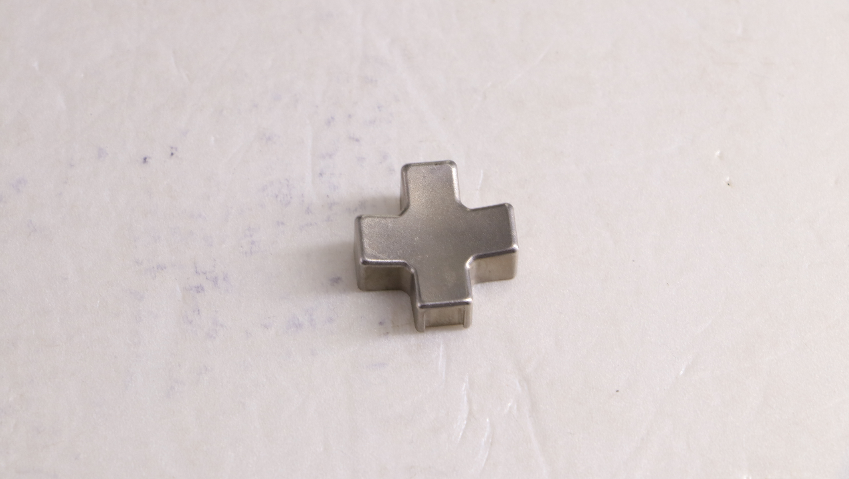
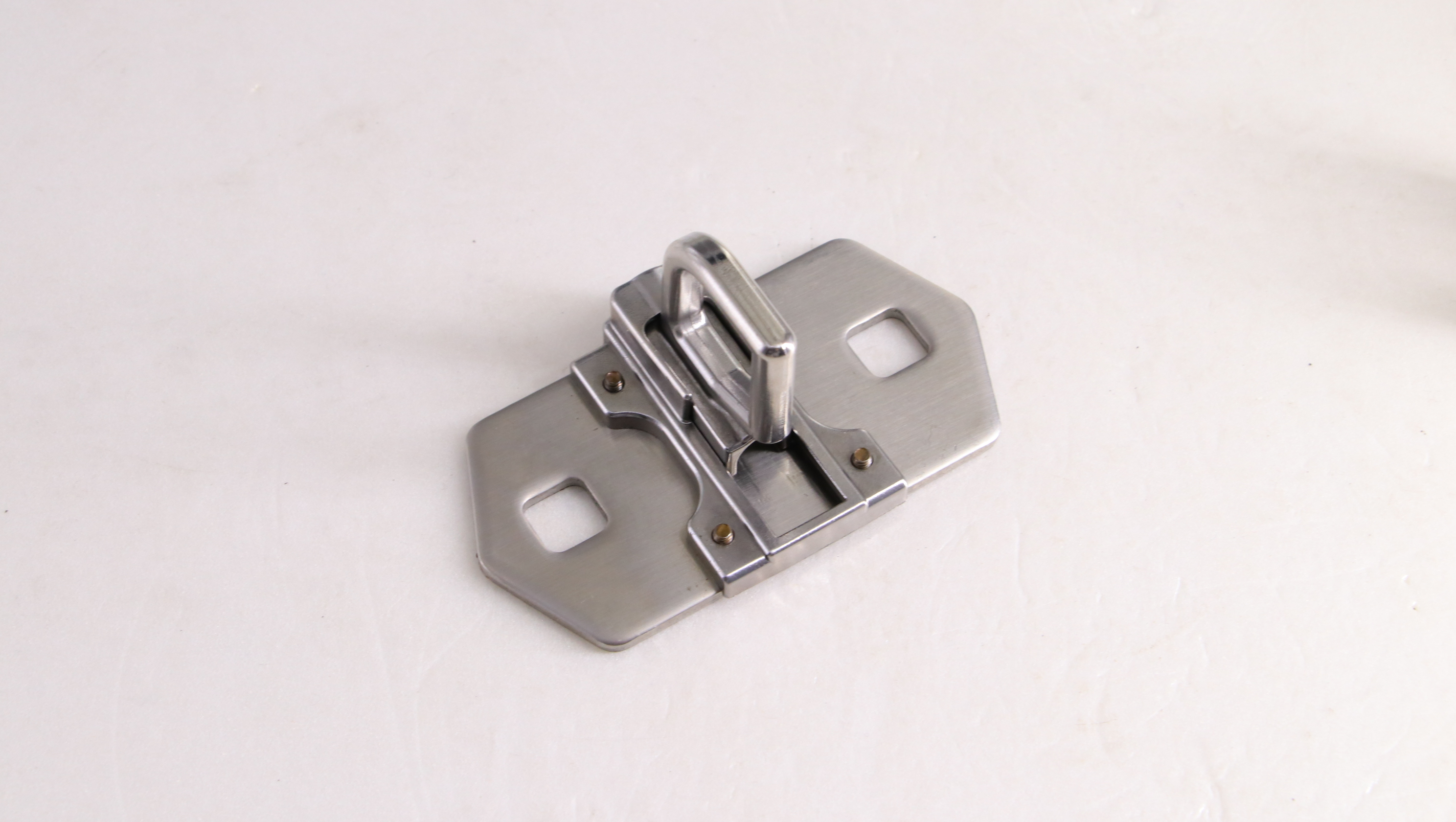
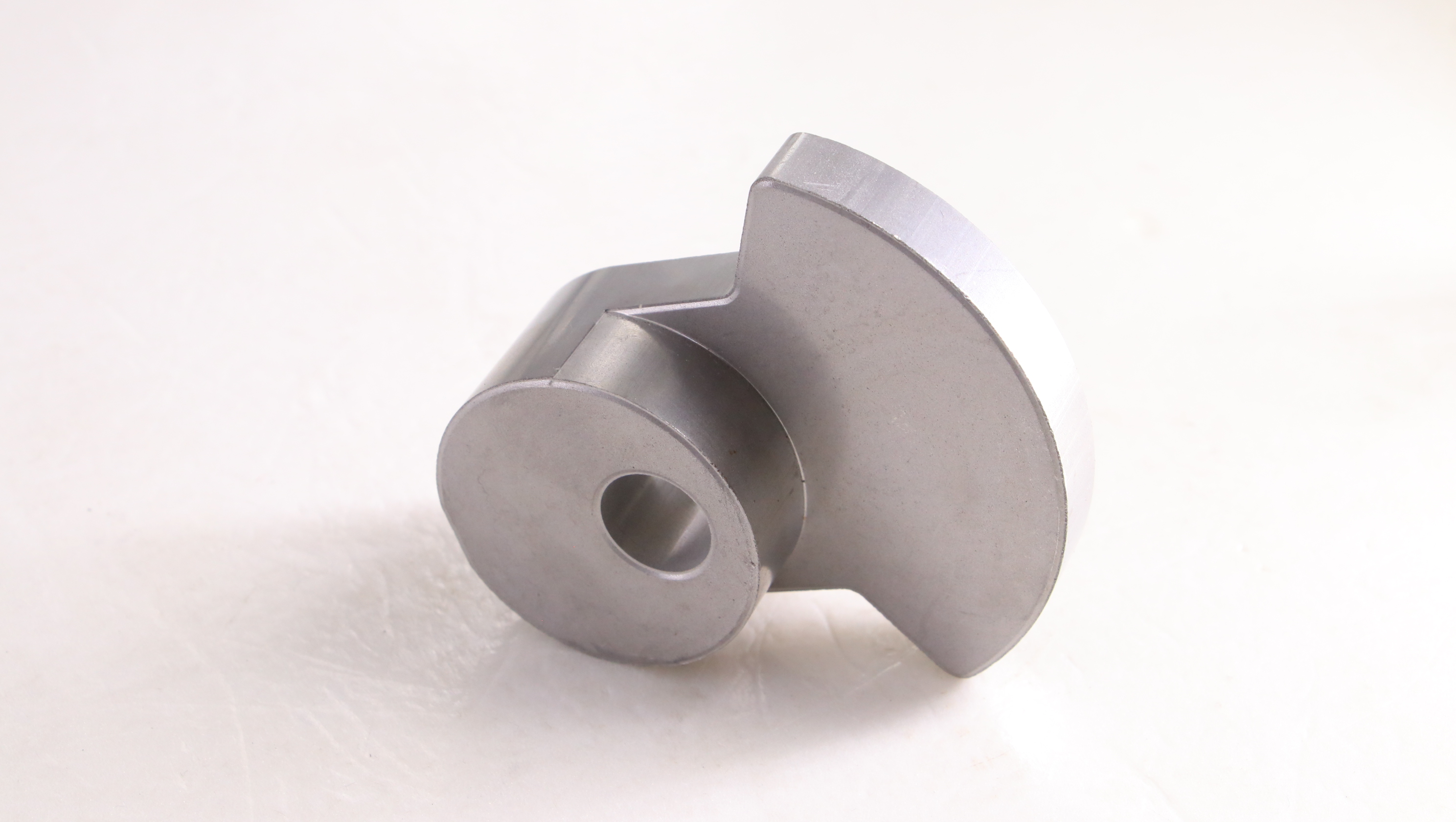
Features including thinwalls, specialshaped curved surfaces, intersecting holes, blind holes, inner grooves, fine ribs, hollowout features, microteeth and complex undercuts.
MIM shows prominent advantages if CNC requires multistation operations, repeated clamping and substantial material removal.
Threads, small gears and specialshaped profiles can be directly formed to reduce secondary machining.
3. Volume Requirements
Most costeffective for annual output ≥10 000 pieces.
Feasible for several thousand pieces, yet high amortization for mold and feedstock tuning results in no unitcost benefit.
Exercise caution for smallbatch runs of several hundred pieces due to high sampling costs.
4. Wallthickness Specifications
Preferred wall thickness: 0.74 mm.
Minimum practical wall thickness: 0.30.5 mm.
Avoid drastic wallthickness variation (e.g. 0.4 mm on one side and 8 mm on the other), which causes warpage, cracking and uneven density during sintering.
5. MIMsuitable Materials
316L, 174PH, 420 stainless steel, ironnickel alloys, Ti6Al4V titanium alloy, copper alloys, tungsten alloys, soft magnetic alloys, etc.
6. Performance Expectations
Target mechanical properties close to forgings; reject casting porosity defects; allow minor postmachining on critical dimensions.
II. Scenarios Where MIM is Not Recommended ❌
1. Largevolume parts over 250 g.
2. Local wall thickness exceeding 10 mm, prone to internal defects.
3. Lowvolume production: several hundred units or prototypeonly orders, high costs for mold opening, debinding and sintering trials.
4. Ultrahigh local precision: dimensional tolerance better than ±0.03 mm cannot be achieved by assintered MIM blanks; secondary CNC finishing is mandatory.
5. Simple blocks or plain pin shafts; press powder metallurgy, cold heading or CNC machining deliver lower costs.
6. Abrupt wallthickness transition without fillet radii.
7. Extralarge flat surfaces, subject to severe sintering warpage.
III. Tolerance Reference (Critical)
Assintered MIM blank tolerance: ±0.3% ~ ±0.5% of part dimension.
General noncritical dimensions: ±0.05 ~ ±0.1 mm.
For tolerance ±0.01 ~ ±0.03 mm: machining allowance must be reserved for subsequent CNC / grinding finishing.
Do not assign tight tolerances to all dimensions; restrict tight tolerances only to critical features.
Surface roughness: assintered Ra 0.81.6 μm; polished down to Ra 0.4 μm.
IV. MIM Part Design Pitfall Checklist
1. Apply fillet radius R≥0.15 mm at all corners; avoid sharp right angles to prevent cracking during debinding and sintering.
2. Eliminate sharp corners and ultrathin ribs; reinforce long cantilever structures.
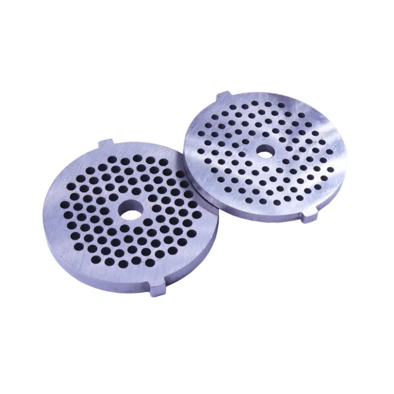
3. Holes: stable performance for bore diameter ≥0.8 mm; depthtodiameter ratio ≤8 for deep holes.
4. Draft angle: 0.51.5° recommended for inner & outer walls for easy greenpart ejection.
5. Avoid large fullyenclosed cavities.
6. Use sloped fillet transitions between thick and thin sections; reject abrupt step changes.
7. Highprecision threads are not recommended to be directly formed by MIM; tapping after sintering is preferred.
V. Practical Project Guidance for Factory Communication
1. Preevaluation: Submit 3D drawings, specify weight, annual output, material, dimensional tolerances, surface requirements, heat treatment and plating requirements.
2. Prototyping: MIM prototypes include softtool samples and formal steeltool samples. Soft
tool samples are lowcost yet unstable for mechanical performance, only for shape validation. Use formal steel molds for performance verification.
3. Cost analysis: Major MIM cost drivers: mold cost, feedstock material, debinding & sintering. Unit cost decreases significantly with higher volume for smallsize parts.
4. Risk assessment: Shrinkage and warpage represent the primary MIM risks. Consult MIM manufacturers for structural modification at design stage, avoid revisions after drawing finalization.
5. Costperformance compromise: Form complex main body via MIM; reserve machining allowances for a few highprecision holes / surfaces with limited CNC postprocessing to balance cost and accuracy.
Powder Metallurgy | Metal Injection Molding | Powder Metallurgy Gears
Guangming Group specializes in R&D and manufacturing of metal forming technologies and wearresistant materials. Main products cover powder metallurgy components by both powder compaction and metal injection molding.
The company boasts a highcaliber talent team. The founding team originates from Guangzhou Institute of NonFerrous Metals, a former national ministeriallevel research institute, with profound industry experience and R&D strength to sustain continuous innovation.
The Group holds 5 invention patents and more than 30 utility model patents. It has obtained certifications including IATF16949, ISO90012015 Quality Management System, ISO14001 Environmental Management System and Intellectual Property Management System, together with international trademark registration.
Guangming Group is recognized as an Innovative Enterprise in Guangdong Province, Guangzhou Science & Technology Little Giant Enterprise, director member unit of Guangdong Powder Metallurgy Industry Technology Innovation Alliance and initiator of Guangzhou Advanced Powder Metallurgy Cluster Promotion Center.
We use cookies to offer you a better browsing experience, analyze site traffic and personalize content. By using this site, you agree to our use of cookies. Privacy Policy